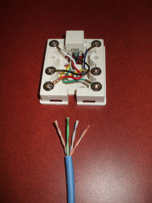
Essential Aspects of Ethernet Wall Jack Wiring Diagram
Ethernet wall jack wiring diagrams serve as blueprints for the installation of network connectivity in residential and commercial settings. Understanding the essential aspects of these diagrams is crucial to ensure reliable and efficient network infrastructure.
1. Cable Type and Length: Diagrams specify the type of Ethernet cable to be used, such as Cat5e, Cat6, or Cat6a. The length of the cable is also indicated, which determines the maximum distance between the wall jack and the network device.
2. Jack Orientation: Jacks are mounted on the wall to provide a physical connection for Ethernet cables. Diagrams show the orientation of the jack, which can be either standard or upside-down. This orientation affects the way the cable is terminated in the wall.
3. Color Coding and Pin Assignments: Ethernet cables use color-coded wires to maintain consistency in wiring. Diagrams provide the color coding scheme and the corresponding pin assignments for the jack. Proper adherence to these standards ensures correct signal transmission.
4. Grounding: Grounding is essential for minimizing electrical interference on Ethernet cables. Diagrams indicate the points where grounding wires should be connected, typically to a grounded outlet box or a dedicated ground wire.
5. Testing and Troubleshooting: Once the wiring is complete, testing is required to verify connectivity. Diagrams provide guidance on the testing procedures and the expected results. Troubleshooting tips are also included to help identify and resolve any issues.
6. Multiple Jacks and Ports: For increased network flexibility, diagrams may include multiple wall jacks or ports. This allows for the connection of multiple devices simultaneously, such as a computer, printer, and IP phone.
7. PoE Support: Power over Ethernet (PoE) enables devices to receive power over the Ethernet cable itself. Diagrams indicate whether the jack supports PoE and provide the necessary pin assignments for power transmission.
Understanding these essential aspects of Ethernet wall jack wiring diagrams empowers installers and network administrators with the knowledge necessary to design and maintain reliable network connections. By following these guidelines, it is possible to ensure optimal performance and connectivity throughout the entire network.

How To Wire Up Ethernet Wall Jacks Cat5e Cat6 Cat7 Keystone Jack Wiring Tutorial Switched On Network

How To Install An Ethernet Jack In A Wall 14 Steps

Ethernet Wall Socket Wiring Diagram Rj45 Jack

How To Wire Up Ethernet Wall Jacks Cat5e Cat6 Cat7 Keystone Jack Wiring Tutorial Switched On Network

Wiring A Home Ethernet Network Practical Beginners Guide

Rj45 Socket Wiring Electrical Circuit Diagram Design

Data Wiring Cat6
What Connector Is Used On A Cat1 Twisted Pair Quora

Commercial Electric Network And Coax Wall Plate 217f 8c Wh The Home Depot

How To Install A Dsl Line
